Showing posts with label How hard can it be?. Show all posts

Wednesday, 16 July 2014

Roofing...

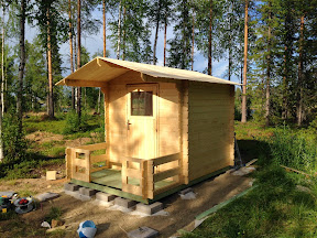
Finally the felt is installed on the roof and the play house starts to look complete. The edges of the felt in front and back need trimming, and some more planks need attaching, but it's getting there now. The final job will be painting.

The felt came in precisely precut sheets of a metre in length. They are installed in such a way, that they overlap to give the impression of tiles. They are nailed to the roof underneath, and the nails must be placed where they will be covered up by the next layer. The work always goes from the outer edge of the roof up to the summit, so that water cannot penetrate between the layers.

The material has a plastic sheet at the back, which must be peeled off first, and then the sheet will stick to the under underneath. The heat of the Sun makes the melt together, or then one can use a heat gun to speed things up when rain is approaching — like tonight.


This is what the house looks like now. Besides the roof, the floor boards of the terrace need some fine tuning at the entrance, and the railing around the terrace will get a flat top. Then we'll be done.

Sunday, 13 July 2014

Play house: Floor - tick; roof - tick ...

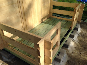
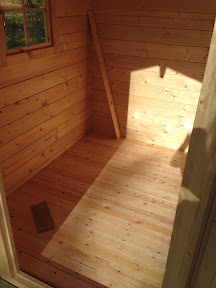
Today our play house got its floor and roof. First we jacked up the three inner foundation beams to make sure they are level. A little padding and all is good. Then we installed the floor of the terrace, and then the floor inside (photos above and below, respectively).

In order to allow the wooden structure to move a bit over time, gaps must be left between the panels of 1-1.5 mm and 5 mm around the edges. The gaps between the floor boards of the terrace are about a centimetre wide.

This gave us good ground for a ladder in order to put the roof panelling in place. Starting from front to back, and one side at a time, the panels were installed — again making sure that there's a 1-1.5 mm gap between the individual panels.

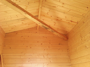
What about the diagonal beam under the roof? As explained in yesterday's blog post despite all care, the whole structure was skewed and while both diagonals at the bottom were as precisely the same as can be (to 1 mm), at the top the diagonals differed by some 2 cm! This was fixed by putting the beam in place after cutting it to exactly the correct length of the diagonal. Once installed, both diagonals matched also at the top.

Now that everything is in place and the roof is on, the tension's gone elsewhere and the diagonal beam is lying loose without any pressure on it, secured by a few nails.

This is what it looks like now, after completion of this stage.

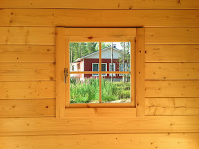
Finally a photo of Our House as seen from inside the play house. Tomorrow we plan to continue with putting the bitumen tiles on the roof and possibly giving the play house a first coat of primer paint in order to protect it from the elements.

By the way, the play house is a kit marketed as "Lillevilla 209" or "Lillevilla Playhouse 4", a product from Finland, which is available elsewhere in Europe, too.

Saturday, 12 July 2014

Building a play house


Finally, the play house project is taking shape. We bought a kit in late May, and began by surveying the location. We used concrete tiles as foundations, and it is very important to get all tiles exactly to the correct height, or otherwise the log construction will be skewed. We also put down a large sheet of geotextile to prevent vegetation from growing under the house.

The next step was to put down five foundation beams of wood, and the first layer of logs on top of that. Here, again, it is very important to have everything level, and to be absolutely sure that both diagonals are of the same length, or otherwise the house will not have right angles and things like window and door won't fit properly. So it takes ages to do all the preparations, but after that it's great fun to see the house grow — a process that we have filmed with our GoPro Hero 2 camera at one image per 5 seconds.


Have a look at the resulting time-lapse film, which is just over a minute long. Enjoy!


The final photo above shows what it looks like now. The cargo lashings inside are needed, because despite all accuracy with getting everything aligned just right, wood is a natural material and everything was slightly off direction and needed careful nudging into the right place.


Tuesday, 27 August 2013

Wheelbarrow "Spring Over"

Besides having that red heavy-duty wheelbarrow, we decided it was time to buy a normal one for smaller jobs around Our House. Yeah, ok, it doesn't have a winch – but it's yellow! Anyway, the instructions clearly said to mount the axle (indicated by the yellow arrow, click to enlarge) on top of the frame. However, when lifting the wheel barrow on the handle bars, the arch in front of the wheel went so low, that it rammed into any minor obstacle and thereby made moving around on anything but a flat path impossible.

The problem reminded me of an improvement some off-road people do to their 4x4s, which is called "Spring Over Axle" conversion. The idea is that instead of hanging the leaf springs under the axle, they are mounted on top of it, thus giving a lot more ground clearance. Here a "Frame Over" conversion was called for.

The implementation of this on something as basic as a wheel barrow is shown in the photo montage above, which shows both before and after. The axle is at the same location in both photos (arrow), but it has been changed from mounted above to mounted below the frame, thereby lifting the front arch by some 7 cm or so, but at the same time lowering the handle bars and tilting the whole thing backwards. The result: it works! Much better than before!

Photos: Thomas Ulich.

Thursday, 14 June 2012

Project Doll's House: Let's build it!

Now then, let's make it, and find out, if the theory is any good in practice. In the previous post, there's a list of elements to cut out, and a suggestion in which order this could be done. The first step is to cut the ground plane, the rear wall, and both side walls. I suggest to leave the side walls rectangular at this stage, since it is time-consuming to cut the exact roof shape only to find out that something else went wrong. Therefore I really recommend to leave the roof until all the other bits fit together – contrary to what I did and what is shown in the photos.

After cutting out these four elements, 5 mm deep grooves are cut into the ground plane, into which the walls will be seated. Now we can make a first test and see if everything fits together so far. This also serves as a motivation boost for you and most importantly for the little girl waiting for her doll's house: "Daddy, you can REALLY do that!"

The next step is to cut out the two floors, and to cut grooves into the side and rear walls to receive the floors. Again, it's time to try the arrangement immediately, just to see how the project takes shape.

The next step is to cut out the interior walls, and then make the grooves for them to sit in. Apart from working out the exact shape of the roof for the folding mechanism, this is the trickiest bit, because it requires – even more than before – precision measurements and work. In the photo above, the interior walls already have doors in them. The doors and staircase will be explained in the next post.

I did not manage to get all grooves exactly lined up, and an offset of a few millimetre is visible in the front between the first-floor wall and the second-floor walls. Since a lot of effort and time went into this, and the winter was fast approaching (I have to do these things outside!), that we decided to leave it at that and not try to redo the lower floor and the ground plane.

The final result looks already a lot like a doll's house, with expectations and excitement clearly on the rise – and Christmas on the horizon! At this point it's worth mentioning, that the house in the picture above is held together by exactly two small nails on the upper rear corners of side and rear walls. Everything else just slots into grooves.

Now that we are at a stage that all major elements are cut out and everything fits together well, it is time to cut the top bits of the side walls into the proper shape for the roof and to cut out the doors and elements for the stair cases. Then it'll be time to plan size and location of the windows. Finally, the whole thing will have to come apart for painting. To be continued...

Photos and design: Thomas Ulich.

Sunday, 10 June 2012

Project Doll's House: Summary of Measurements

After so much theory and thinking, maybe it is time to make a simple summary list of the elements we need to cut. If you trust your planning, you can now cut all at once, but maybe it is wise to cut and groove only some parts, and then see if everything fits, before cutting more.

However, we first need to finish some missing bits of the theory, we need to determine the overall height of the doll's house. Previously, we discussed the height of the rooms, and the roof-folding mechanism. All of this we need to put together now, in order to work out the height of side and rear walls.

First, let's decide here, that the ground plane will have 5 mm deep grooves to receive the side and rear walls.

The rear wall needs to cover two floors of 200 mm each, which we said should include the thickness of the floor element (9 mm), i.e. the free room height will be 191 mm. Thus two floors need 2 x 200 mm = 400 mm wall height. To this we need to add 11 mm as detailed earlier, and we need to add another 5 mm to account for the bit the wall will sink into the floor. Thus the rear wall will be 416 mm tall and, as determined previously, 782 mm - 2 x 7 mm = 768 mm wide (7 mm for grooves in both side walls).

The side walls are a bit more complicated, but let's first only cut out two rectangular pieces of wood, after which we will transfer the measurements of the roof-folding mechanism to these elements and cut out the details in another step. The side wall needs to have the same height as the rear wall up to the point, where the roof section starts, i.e. up to the place from where we will later make 45° cuts. Thus we know that the lower bit is 416 mm tall (see above). From the post about the roof-folding mechanism (drawing), we can see that the height above that line is 180 mm + 12.7 mm + 20 mm = 212.7 mm, which gives a total height of 628.7 mm. Previously we already worked out the width of the side wall to be 360 mm.

Now then, here's the list:
  • Ground plane, 12-mm plywood, 420 mm x 842 mm (from here)
  • Side walls, 12-mm plywood, 360 mm x 628.7 mm (2 pieces; see above)
  • Rear wall, 9-mm plywood, 768 mm x 416 mm (see above)
  • Floors, 9-mm plywood, 764 mm x 354 mm (from here)
  • Internal walls, 9-mm plywood, 197 mm x 354 mm (from here)
Thus a practical approach is:
  1. Cut ground plane, side walls, rear wall.
  2. Make 5 mm deep grooves in ground plane for the outer walls, side walls 12 mm width, rear walls 9 mm.
  3. Make grooves along the rear edges of the side walls, so that side and rear walls overlap as shown here.
  4. Put it all together. This is always a motivating highlight. Repeat often.
  5. If ok so far, copy the outline of the roof-folding mechanism onto the side walls, and cut out accordingly.
  6. Put it all together.
  7. Cut floors.
  8. Make 3 mm deep grooves in side and rear walls for floors, make sure they align properly.
  9. Put it all together.
  10. Cut interior walls.
  11. Make 3 mm deep grooves for interior walls.
  12. Put it all together.
After all this you should have:

In the next post, I will show the build stages outlined here.

Design and photo: Thomas Ulich.

Tuesday, 29 May 2012

Project Doll's House: Wall Heights

The height of the side walls is of course determined by the height of the rooms. As discussed previously, a reasonable room height is 2.40 m or 20 cm. In order to make this easier, I decided to make the distance floor-to-floor 200 mm, and thus for my choice of 9-mm plywood, this leaves a room height of 191 mm or 2.29 m in real life, which is still very realistic. For two floors, this makes 400 mm wall height.

However, it would not be good to have the roof rest directly on the floor, and therefore I added 11 mm more height. The reason for my choice of 11 mm is that the 45° inclined roof will have an internal maximum height of 180 mm, and adding 11 mm will make this the same room height as in the lower floors: 191 mm. Due to the inclination of the roof, this is somewhat arbitrary, but it seemed logical at the time, and turned out to work well in the end. See the drawing for details (click for larger version).

After fixing these dimensions, also the height of the internal walls was fixed. They should slot into floor and ceiling, into grooves of 3 mm depth. Thus the height of the walls is 197 mm.

Photos and design: Thomas Ulich.

Tuesday, 22 May 2012

Project Doll's House: Roof Mechanism

Wouldn't it be fun to have a roof that opens and closes? — Because the roof panel is slightly wider than the house (822 mm) and, assuming a 45° slope, 295 mm wide, it will be somewhat heavy and will require sturdy hinges in order to survive frequent opening and closing. Since the roof material is thin (9 mm), one cannot easily use screws to attach hinges. One could use bolts, but these would show on the outside and look ugly. Therefore I designed an opening mechanism, which is based upon nothing but the shape of the walls and roof. Here's the plan (click for larger version).

The roof is sloped by 45°, i.e. for a 360 mm wide house, the roof will be 180 mm high in the middle. The roof elements need to be a little larger on both sides (here 20 mm on either side), and also "hang over" the edge to front and rear, i.e. 20 mm wider.

The side wall needs to have a square-shaped bit on the top, into which one can cut a circular hole for slotting in a part of the roof. All of this is designed in such a way that the front roof panel lies flat on the side wall when closed, and flat on the rear part of the roof when open. See the detail photo for what this looks like in practice.

Working out the exact measurements, and then triple-checking everything before cutting the wood, was probably the trickiest bit in the whole project.

Ok, now we know the shape of the roof, but how tall do the outer walls need to be, and where do the floors slot in? More on that in the next blog post...

Photos and design: Thomas Ulich.

Monday, 14 May 2012

Project Doll's House: Measurements and Materials

The project of building a doll's house continued with the choice of materials, and then the definition of the room sizes and measurements, which are needed to cut the wood. For the outer walls I chose standard plywood of 12 mm thickness, and 9 mm plywood for the interior walls, the floors, and the roof.


Thus the 12-mm ground plane onto which the house is built, is 420 mm by 842 mm. Forty-two is for some reason always a welcome size. Centred on this there are the outer walls, of which the left and right walls are of 12-mm plywood and the rear wall is of 9-mm plywood. The outer dimension of the doll's house is 360 mm by 782 mm.

The room sizes were chosen such that the bigger room (living room) is 330 mm by 351 mm, which is equivalent to 3.96 m by 4.21 m. The staircase is 160 mm wide (1.92 m), and the smaller room is 250 mm (3.00 m) wide.

Note, that the lengths of the internal walls (staircase walls) is 3 mm longer than needed judging from the size of the rooms. The reason for this is that the rear wall has 3 mm deep grooves which the walls slot into for stability.

Note further, that also the 12 mm walls were grooved with a 5 mm deep and 9 mm wide groove, into which the rear wall fits. See the detail photograph to illustrate this.

Since the horizontal dimensions are fixed now, also the size of the two floors/ceilings is fixed. These should slot into the side walls and into the rear wall. The grooves are 3 mm deep, and therefore the floor material has to be cut to a size 6 mm wider in the long direction, and 3 mm wider in the narrow direction than the internal width of the doll's house, i.e. 764 mm by 354 mm.

Next step was to think about the exact shape of the roof and thus the wall underneath. This included the invention of a hingeless opening mechanism for the roof. More about this in the next blog post.

Photos and design: Thomas Ulich.

Tuesday, 8 May 2012

Project Doll's House

So, your daughter would love to have a doll's house? No problem, a few clicks on the internet, and Santa is tipped off and knows what to bring. Easy. But then you realise, doll's houses, at least the nice ones, are expensive, and looking at your shed you think, "I can do that myself! How hard can it be?"

Now then, first the planning phase. How many floors? How wide? How tall? Should there be windows? What about a staircase? — Some brief investigation on the interweb, and one finds that a common scale for doll's houses is 1:12. This might come from the fact that there are 12 inches to the foot, or for the metric world, a doll's house featuring a floor-to-ceiling height of 20 cm is equivalent to a room height of 2.40 m in the real world, which is pretty much standard. Now that we know the scale, paper and pencil will do the rest. Here's the first draft (click for bigger version):


So the doll's house planned here will have two full floors and an accessible attic. The attic will be one large room, and the floors will each have one large room, one small room, and a staircase/corridor. The sizes of the rooms in this plan are not final yet, but they give the right direction. A room of 3 m by 3 m is rather small and does not fit large furniture well. Therefore planning for a living room of 4 m by 4 m or so makes sense. This means roughly 34 cm width. The staircase should be two metres wide, that's roughly 16 cm in the doll's world. The staircase is planned with half-way landings, and then folding back. The smaller room could be 3 m wide or so, which means 25 cm. Then one needs to account for the width of the walls, and the base plate should maybe be a couple of cm wider on all sides. Thus we easily end up with a house of something like 75 cm wide, 40 cm deep, and 60 cm high. Yes, that's big...

In the next blog post, I will discuss the exact measurements.

Photo and design: Thomas Ulich.

Sunday, 1 May 2011

Building a silent computer

This is a tricky one. There are so many zillions of PC-type computers out there, and so many components to build a computer for a purpose, that it is very hard to find an ideal combination of parts. This is not exactly becoming easier, if you live in a location far from any big city. Thus after a lot of searching around in the internet, I simply went to a large computer shop to ask the staff some question. In my case I was lucky and immediately found a very knowledgable sales person, who understood exactly what I wanted, and came up with a custom selection of parts to build a computer, which is quiet enough to sit in the living room near the TV, and which is powerful enough to run three DVB receivers.

In my case one of the requirements was that the mainboard and the case can accommodate three PCI cards. Nowadays, lots of boards do not anymore have that many PCI slots. I have earlier had very bad experience with so-called "riser cards." Riser cards plug into one PCI slot and allow to connect two or three PCI cards to the same port, often at a 90° angle. However, many of these cards are faulty, and if you have very demanding PCI cards, there won't be enough power to both cards through the riser card. Therefore stay away from those. Besides finding the right mainboard, this also meant to find a suitable ATX case, which has enough space to accommodate three cards standing upright straight on the mainboard. The choice of keyboard and mouse was determined by my wanting something that looks nice on the coffee table and that it had to be wireless of course.

Here's the parts list of my solution, but your solution might look very different, since there are so many choices available.

  • CPU: AMD Athlon II X4 640, 3 GHz
  • Mainboard: Asus M4A88TD-V EVO/U w/ on-board graphics with HDMI output
  • Power supply: Corsair TX750W
  • CPU cooler: Scythe Ninja 3
  • RAM: Kingston Valueram 4GB
  • Case: Antec 300 ATX case
  • Harddisk: 2 x Samsung Spinpoint F3, 1 TB
  • DVD/BluRay/CD: Lite-On IHES208-31 DVD+/-RW and Blu-Ray player
  • Mouse: Apple Magic Mouse
  • Keyboard: Apple Wireless Keyboard
  • Bluetooth: cellular line BT Micro Adapter (USB dongle)

In my case, I am using the following two receiver cards, which are widely reported to work well together:

  • Hauppauge WinTV NOVA HD S2 PCI, single DVB-S/S2 tuner for HDTV
  • Hauppauge WinTV NOVA T-500 PCI, dual DVB-T tuner

Experiences:

This hardware turned out to be noisier than I hoped for. On closer inspection it turned out that the Antec 300 case came with two fans, which are not controllable by the mainboard. Instead, they simply have switches dangling about on cables, which allow three fixed settings: low, medium, high. Thus these two will be replaced as soon as possible for temperature controlled fans.

Secondly, I found that the large doors of the case (both panels can be easily opened without tools to give full access to the internals), are resonating and thus making the noise worse. Thus I went to the local car part shop and bought 10mm think adhesive soundproofing for cars, cut it to shape, and stuck it into the box. The result is a much quieter computer, high frequencies and hollow metallic noise are practically gone, and only less disturbant low frequencies are audible. Together with the change of fans, this will be a very quiet machine in the end.

Power supply: the 750W power supply seems a bit over-the-top for a machine like this. The argument here was twofold. A big power supply will not become hot when only small power is drawn, thus its fan won't spin up very high except in rare occasions, which will make for a quieter computer. Secondly, too many computers suffer from too small, i.e. cheap, power supplies, which aren't really up to the job of keeping all the internal components happy. This is expressed, e.g., in memory failures. With this big power supply, I hope I won't encounter any of that.

Saturday, 30 April 2011

A computer to watch TV?

We have an unusual TV setup, we want to receive free-to-air satellite programmes from back home, but we also want to watch the local free-to-air terrestrial TV programmes. Thus we need a combined DVB-T and DVB-S/S2 receiver, that of course should be able to record on harddisk. Such a device is hard to come by in form of a set-top box. In fact thus far I have come across only one, which seems to be based on some Linux derivative and which is modular in that allows for plugging in receiver modules of any kind. However, the price was very high.

The next-best solution is to build a "set-top box" yourself using Linux and a software package called MythTV, which is a free package to watch TV. This package allows you to configure as many different TV cards as you want, limited only, it seems, by the processing power of the computer. MythTV even has a web interface, which allows you to schedule recordings while away from home, and to watch programmes recorded previously. Moreover, the computer can of course be used as a media server for the family, and store the backups of other computers etc.

Here I decided to use the Ubuntu variant of Linux. Over the next several posts, I will document the installation in detail, so that anyone can repeat the process (I hope). Please feel free to comment on the setup, esp. hints on how to do it better are naturally very welcome.